
Posted by GV on Dec 29th 2023
MA70 #3
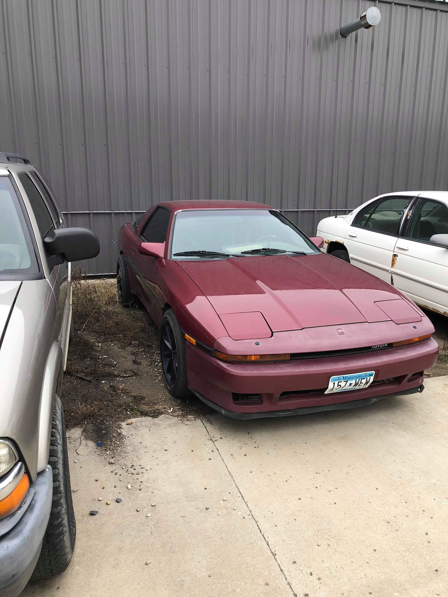
Purchased from a family member, this is my third MA70, first pre-facelift car. It's a slow moving resto-mod project.
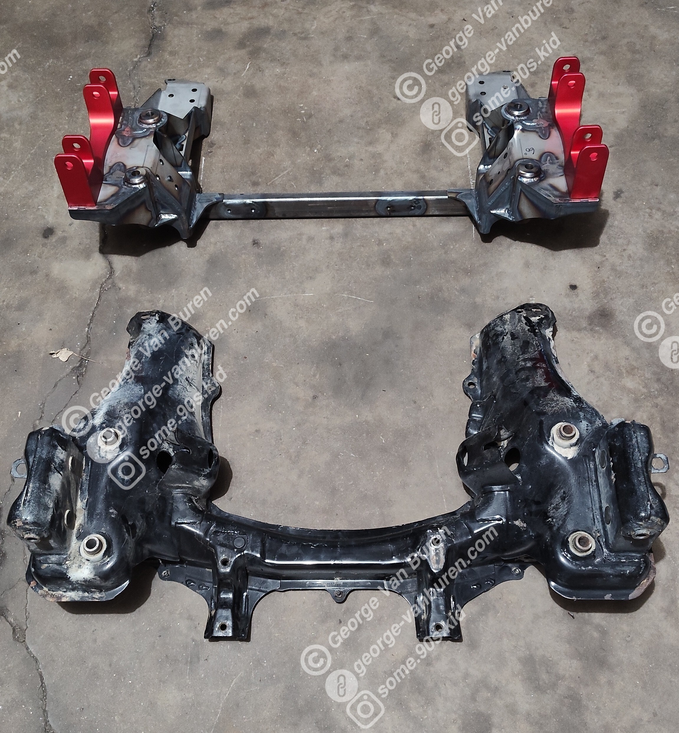
The rear subframes on these cars are becoming increasingly prone to cracking, before it was just from pushing more power through the original parts but as time has passed just excessive miles with low power can do it too. It's also fairly easy to strip out the caged square nuts in the cradle where the snub of the differential bolts too, which is exactly what I did. Because of this I opted to have the entire subframe sandblasted and boy am i glad I did, what I found hiding underneath the paint should be reason enough to inspect these even if there aren't immediate issues. Most of the welds on the cradle were either riddled with porosity or the operator missed the joint to be welded entirely and went back for a second go leaving a plethora of other potential failure points, it makes me think that its these defects that cause the cracks in the first place. Regardless, I had to do surgery to fix the stripped nuts but instead of just replacing them with some hardware store components I decided it would be wise to construct a new cradle entirely and here's why. The original nuts are likely grade 8 hardware to match the grade 8 bolts that hold the front of the differential in place and rolled threads on top of that. The only hardware store parts I could find in the same diameter and thread pitch were grade 5 and likely 75% thread or worse. In the world of threading, cut threads can be made to extreme tolerances however the grain structure of the threads follows the part. Rolled threads can't be held to such tight tolerances but are much like forging, as the grain structure of the threads follows the helix making them stronger. While I did not replace these nuts with rolled thread parts, I made sure that they would be strong enough. They are 1.5" diameter slugs to fit into 1.75" x 0.125" DOM tube (1020 steel) that are made from 4140 chromoly with 9/16 x 18 threads to a 3B fit and are 0.75" tall so plenty of thread engagement. The cradle was cut in the middle and replaced with 1.75" x 0.125" DOM tube which was tied into the remaining cradle structure to retain the original suspension attachment points. I also tied the cradle into the rest of the subframe with a X brace made from 1" x 0.125" DOM tube and have gone over all of the welds on the subframe with a TIG welding process. Plates were welded in to reinforce the mounting holes on the back of the subframe where the differential cover bolts to it, and I have yet to do this so it won't show up in the pictures but there will be 0.125" 1018 steel gussets to tie the 1" tubes into the subframe structure better as most of the subframe is made from very thin material (18 gauge if I had to guess) as well as some reinforcements to the front of the OEM cradle structure to strengthen the spot where I had cut into it to retrieve the square nut prior to jumping into all of this
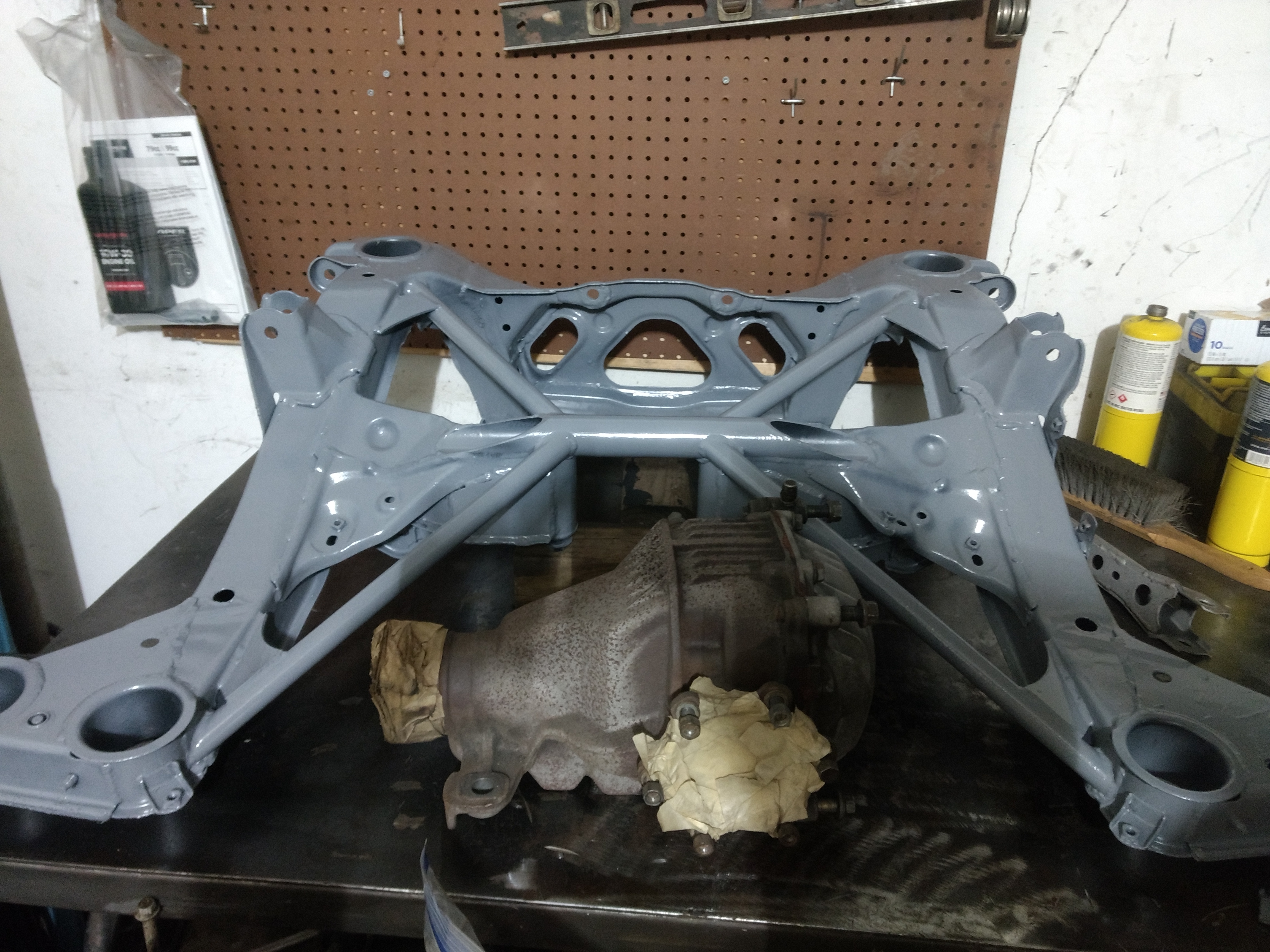
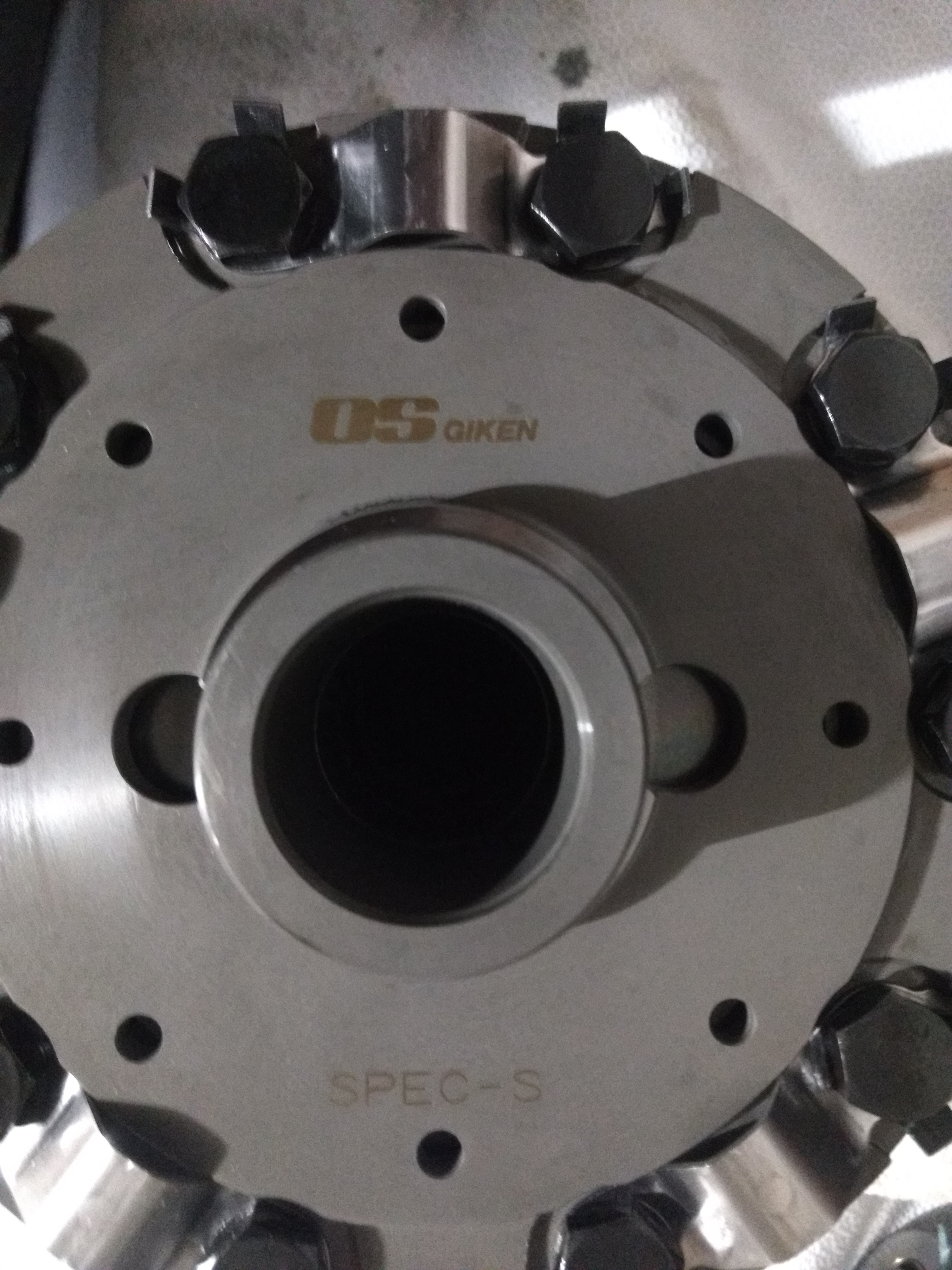
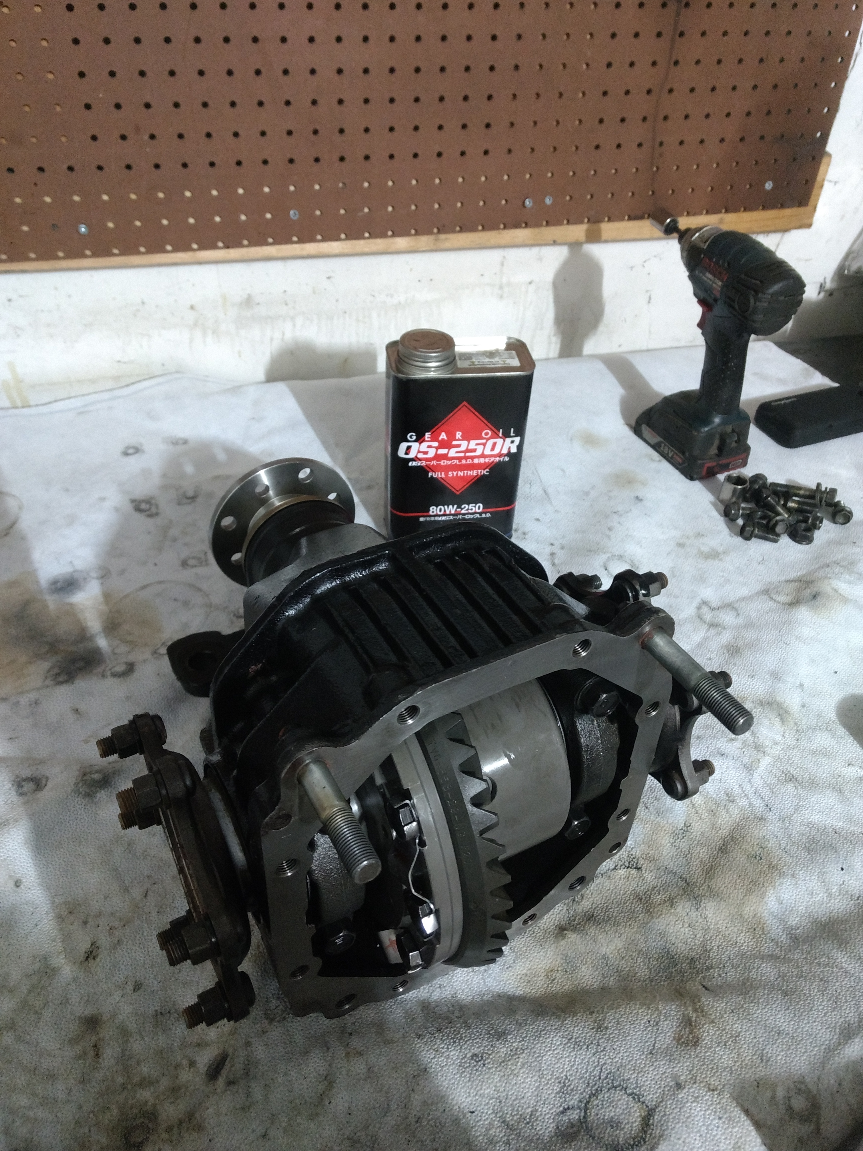
The original unit was a 4.30 ratio stock LSD carrier with the 27 spline input shaft that these came with. This was changed out for 3.58 gears, 29 spline input shaft, and a OS Giken Super Lock LSD unit. I'm tempted to place a temp sensor on the cover to see if extra cooling is necessary, and either install a mocal pump, filter, and cooler or just machine a new diff cover to better resemble that of a euro spec unit.
I found a suitable engine to put in, along with a transmission. More on this when it's in the car and running
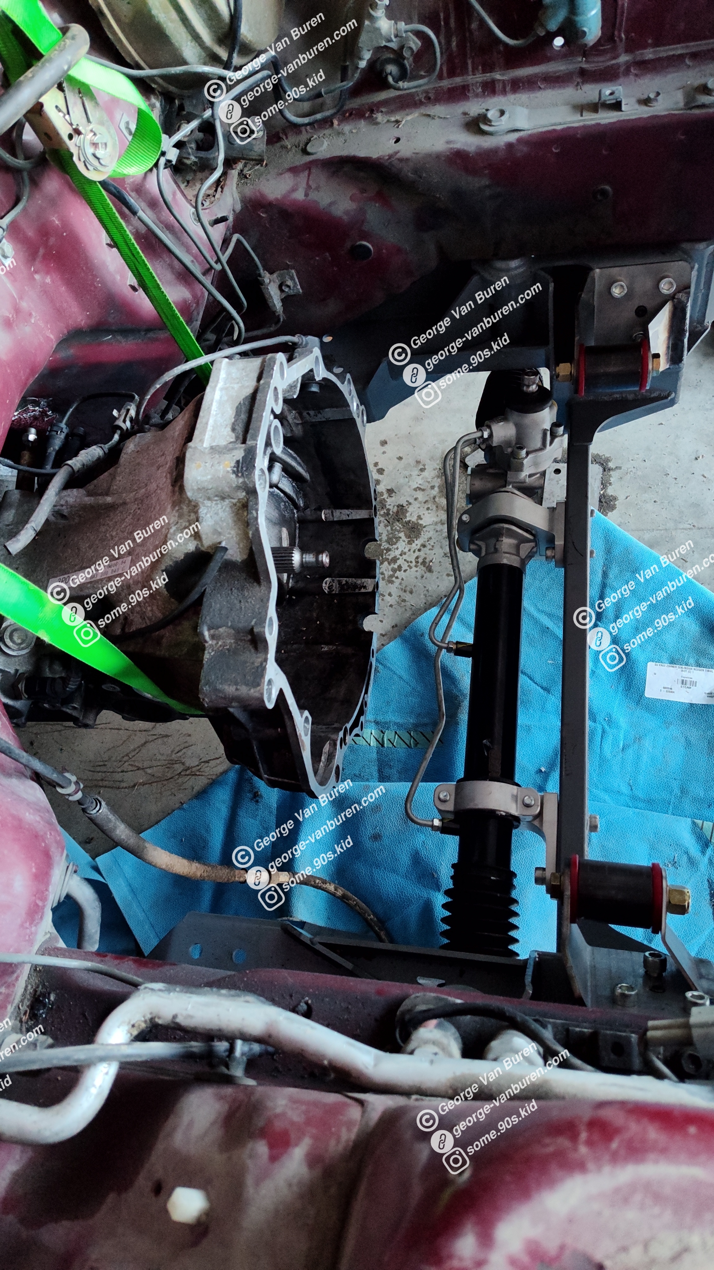
As far as fitting the engine goes, I learned was going to be no quick 5 minute job. While the subframe is designed to surround an engine with a rear sump, the new engine is front sump. And while I would love to take the "easy" road of converting the engine to rear sump, that is in fact, not the easy road. The oil pump is located in the middle of the sump and is shaft driven from the timing set on the back of the engine, which then has a "PTO" of sorts for another shaft to drive the water pump at the front of the engine. The "easiest" way to convert this to anything other than front sump would be to go dry sump and electric water pump, which would net a benefit of ~1.5" of height clearance with the added complexities of the fluid systems.
I opted to change the subframe to accommodate a front sump engine, which requires me to relocate the steering rack to the other side of the front axle centerline as well. While I could achieve this by using a RHD A70 steering rack and flipping it upside down for use in my LHD chassis to ensure the wheels steer left when I turn the steering wheel left, they are fairly hard to find. The next suitable replacement was a steering rack from a Nissan S13 - same steering shaft diameter and spline, larger diameter housing, larger diameter threads for the inner tie rods, overall length is less than that of the MA70 - which is perfect as I can then make spacers that bring it out to the correct width and utilize the OEM A70 tie rods.
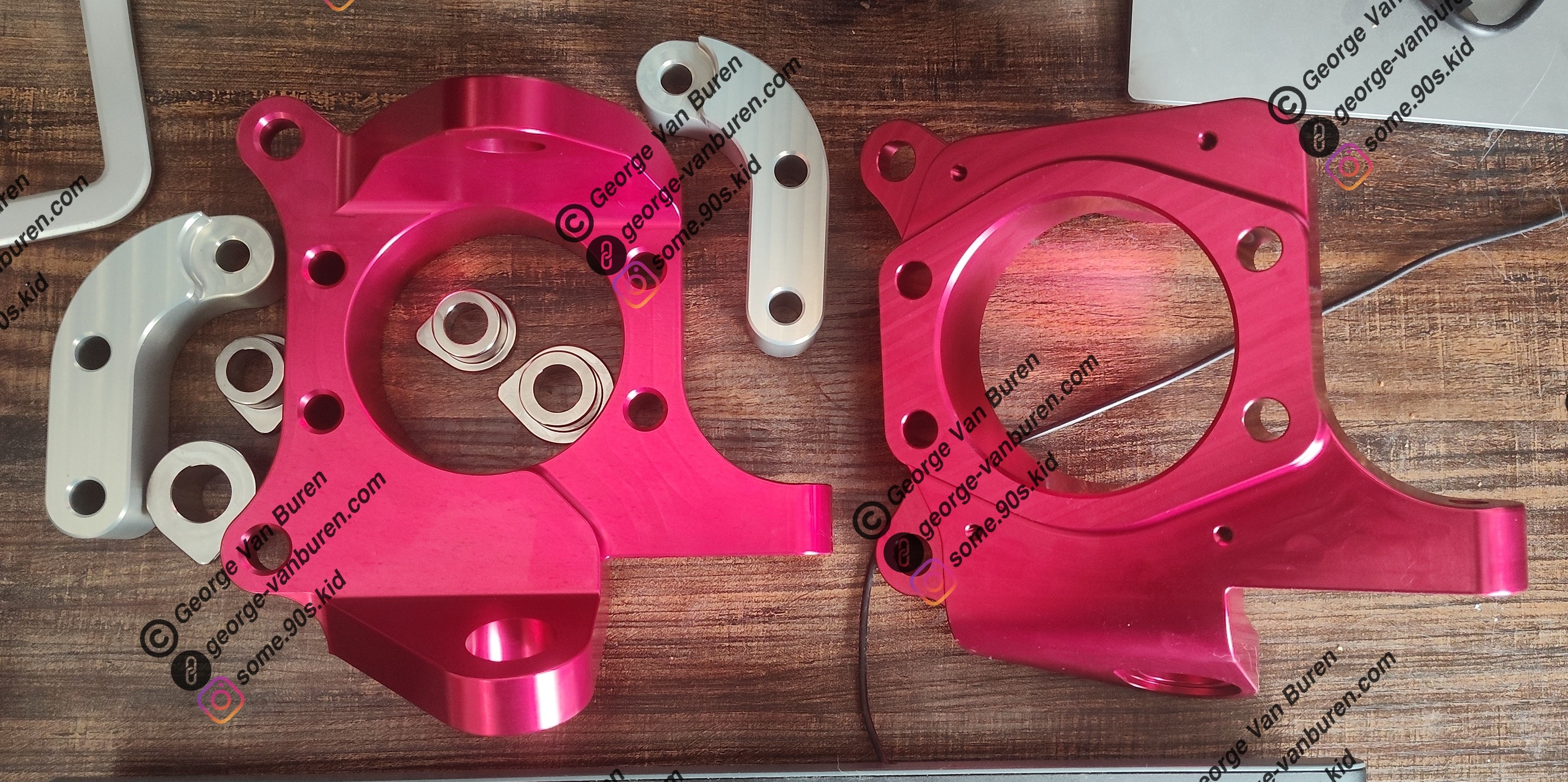
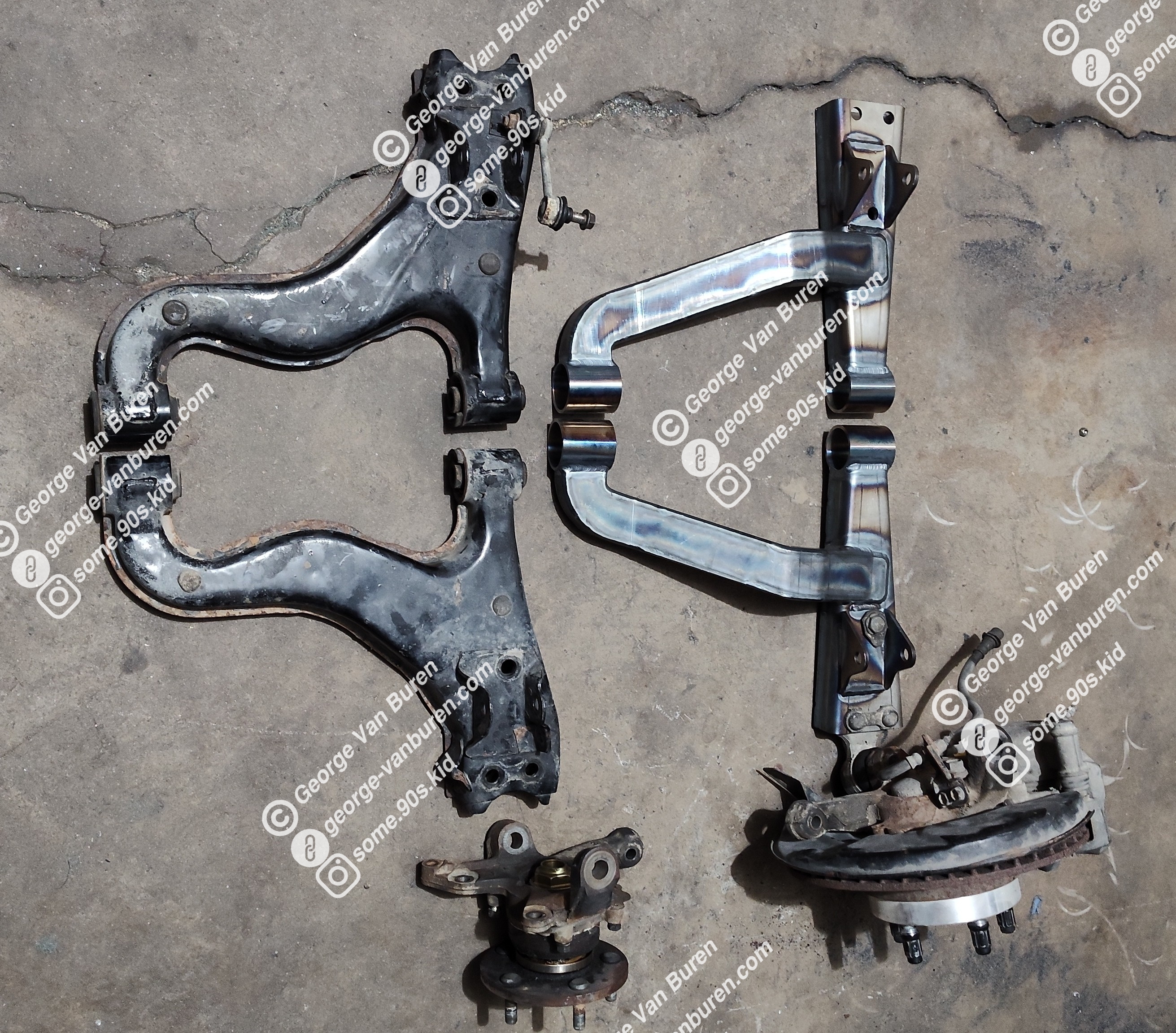
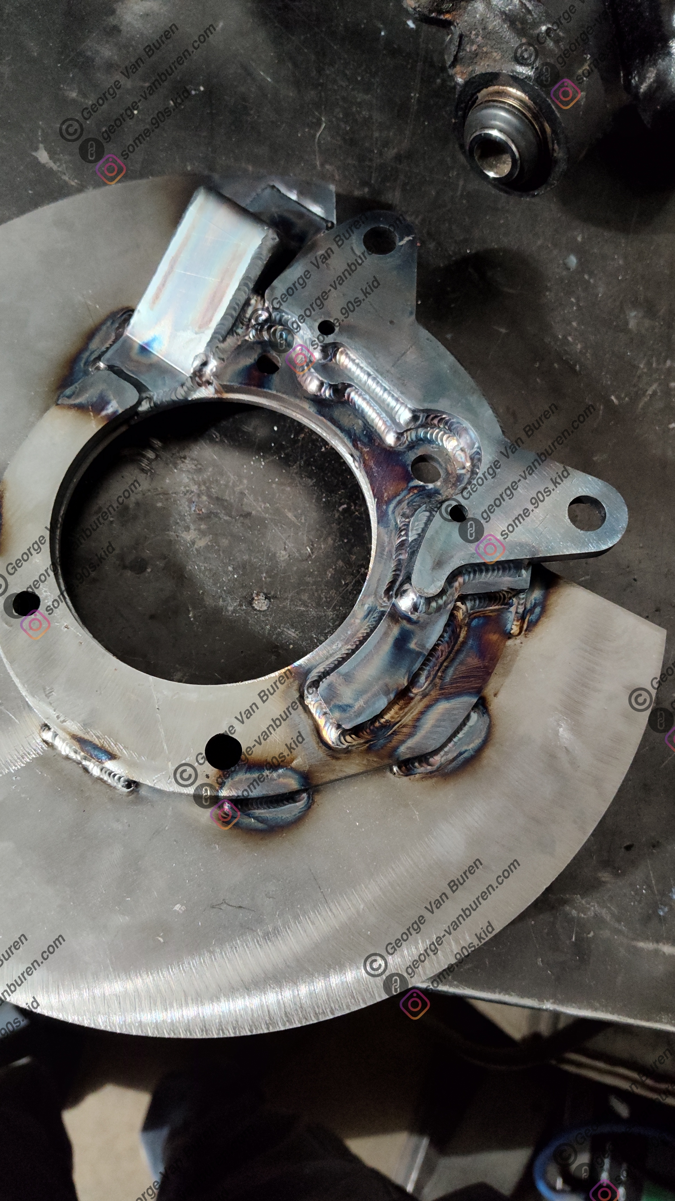
The next task within this endeavor is to make new front knuckles to relocate the mounting ear for the tie rod to the rear side of the axle centerline. Instead of modifying the existing knuckles, I will just make new ones - most likely a solid machined part. I figured while I was there I might as well add provisions for better brakes, as the stock A70 front brakes make use of a 6x mm single piston front caliper and a 305 mm rotor. I opted for 370z Nismo brakes, which use 4 44mm piston calipers and a 355 mm rotor; which is some 25mm larger than the 350z / LS400 brake upgrade. They will also be made to accept 370z wheel bearing cartridges, as it will be much cheaper and easier to machine a new knuckle with a flat face and a bolt pattern than one with a stub for the wheel bearing and hub to be assembled upon.
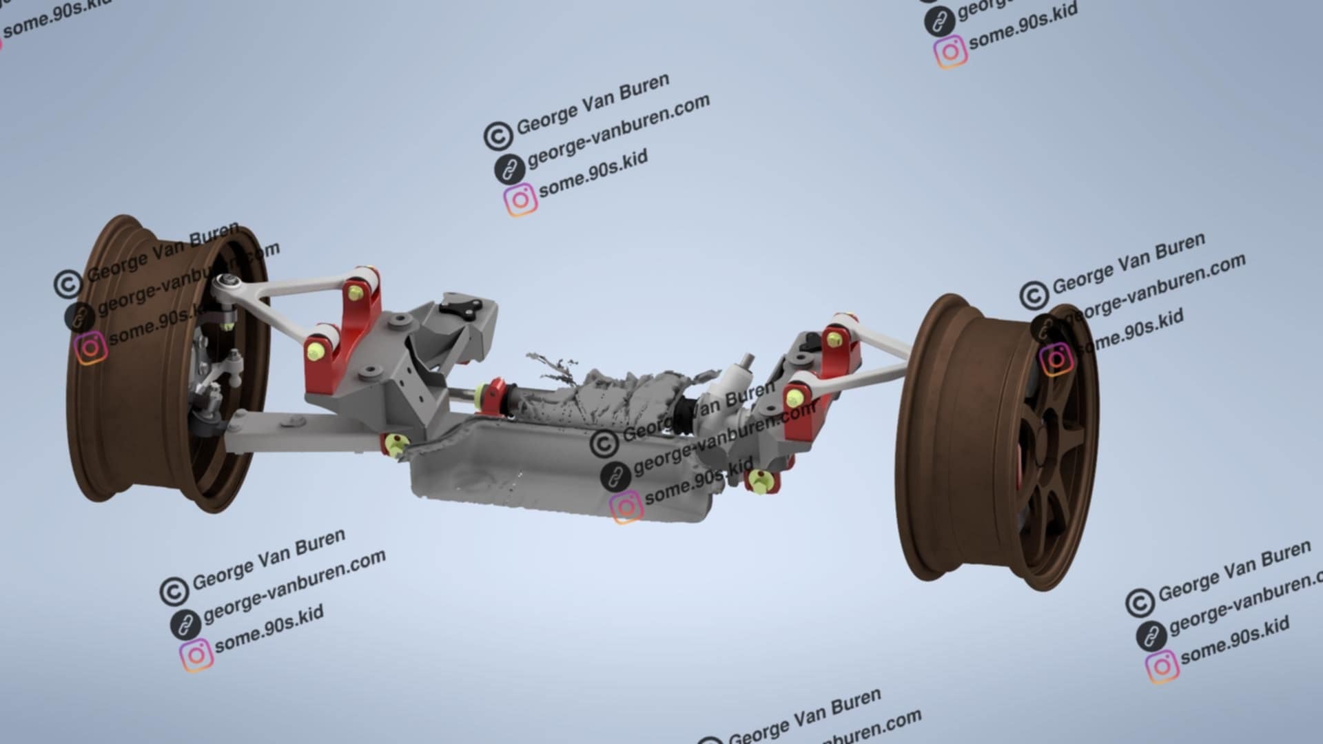
Subframe has been designed to accommodate stock suspension mounting points with location adjustability to be able to adjust RC and camber curve, uses the stock alignment hardware, and uses a S13 steering rack.
The track width has been widened to fit the new steering rack and avoid bump steer, keeping the location of the tie rod pivots in the correct location in relation to the suspension pivot points.
knuckles are roughed with stock suspension pivot point locations in relation to the hub center, they have tabs for the 370z nismo calipers and the tie rod mount relocated to the correct location.
I gathered scan data of the oil pan to ensure all of this will fit
I also compared my model's static alignment and Ackerman angle with the alignment hardware in a neutral position to that specified in the A70 TSRM, accounting for the specified tire size and ride height.
I'm working on comparing the travel rate of the stock NA A70 rack to the S13 rack and plan to change the location of the tie rod tab on the knuckle to favor a quicker steering ratio which will also result in more steering angle.
The suspension mounting points on the subframe and knuckle along with control arm lengths currently match the OEM design, and with the ride height set at 201.5mm and tire size at 225/50r16 (as specified by the A70 TSRM) the RC is at 39mm - without COG data, I'm just comparing the roll center location with the bottom of the car as a comparison with drop knuckles.
So the stock ride height and tire size combo RC to bottom delta is 162.5mm
stock knuckle, lowered 40mm via spring w/ 225/50r16
161.5mm to bottom
4mm to RC
157.5mm delta
40mm drop knuckle w/ 225/50r16 -10mm squish (just a guess)
161.5mm to bottom
31m to RC
130.5mm delta
40mm drop knuckle w/ 255/35/r18 -5mm squish (just a guess at desired tire size and squish, may go with a different size but hoping to be able to get away with 18" wheels with the 370z Nismo brakes)
161.5mm to bottom
25mm to RC
136.5mm delta
making the roll center closer to the center of gravity would reduce body roll and place more of the lateral force form cornering on the tire rather than the shock, it is my assumption (since I don't have track data) that this would be beneficial over lowering with lowering springs.
With the suspension geometry close to figured out, next is figuring out what I want to do with the difference in rack ratios between the A70 rack and the S13 rack.
Here is some data
A70 -travel = 146mm ; turns = 2.9 ; ratio = 7.15 deg/mm
stock knuckle dimensions
=2.4 degrees steering angle @ 45 degrees wheel turn
=4.8 degrees steering angle @ 90 degrees wheel turn
=max of 28.7 degrees of steering angle @ 1.45 wheel turns
S13 -travel = 138mm ; turns = 3.1 ; ratio = 8.09 deg/mm
So the S13 rack has less travel and a slower ratio
stock knuckle dimensions
=max of 27 degrees of steering angle @1.55 wheel turns
Modified knuckle A - supposed to make S13 rack ratio match the stock knuckle a70 rack combo more closely
=2.5 degrees steering angle @ 45 degrees wheel turn
=5 degrees steering angle @ 90 degrees wheel turn
=28.7 degrees steering angle @ 1.45 turns
=max of 30.8 degrees steering angle @ 1.55 wheel turns
Modified knuckle B - supposed to give the car a more sporty feel, but with the loss of fine control at higher speeds
=3.2 degrees steering angle @ 45 degrees wheel turn
=6.4 degrees steering angle @ 90 degrees wheel turn
=28.7 degrees steering angle @ 1.125 wheel turns
=max 40 degrees steering angle @ 1.55 wheel turns
Not entirely sure what I want to do, but the mount for the tie rod on the knuckle and the steering rack mounts on the subframe will all be bolt on parts so it could be changed later. Ackermann angle for the modified knuckles match OEM geometry. All of the RC data was gathered from vsusp
Playing around with subtle changes of the steering geometry, while I have made all of the mounts replaceable and in turn "adjustable" I wanted to get everything as close as I could in CAD to have a solid base. I was seeing some bump steer:
0.0046 deg toe in @ 50mm compression
0.0772 deg toe in @ ride height
0.3200 deg toe in @ 40mm extension
This would net a change of 0.03" of toe out from ride height to compression and 0.125" from extension to compression
(while the suspension travel distances may be extreme, id rather have a larger window to interpolate the data. It would likely be ideal to take toe measurements every 5-10mm of suspension travel and plot it on a graph however as im sure the line is not straight)
I moved the steering rack up 2mm
0.0256 deg toe in @ 50mm compression
0.0226 deg toe in @ ride height
0.1139 deg toe in @ 40mm extension
This would net a change of 0.001" of toe in from ride height to compression and 0.038" of toe out from extension to compression. closer
I moved the rack up another mm
0.034 deg toe in @ 50mm compression
0.074 deg toe out @ ride height
0.008 deg toe in @ 40mm compression
This would net a change of 0.04" of toe in on compression (favorable, helps turn in and stability on braking) and 0.01" of toe in from extension to compression, with 0.035" of toe out between extension and right height. such a small amount and the curve seems to be centered, that I think that tire side wall flex would likely eat it up.
![]()
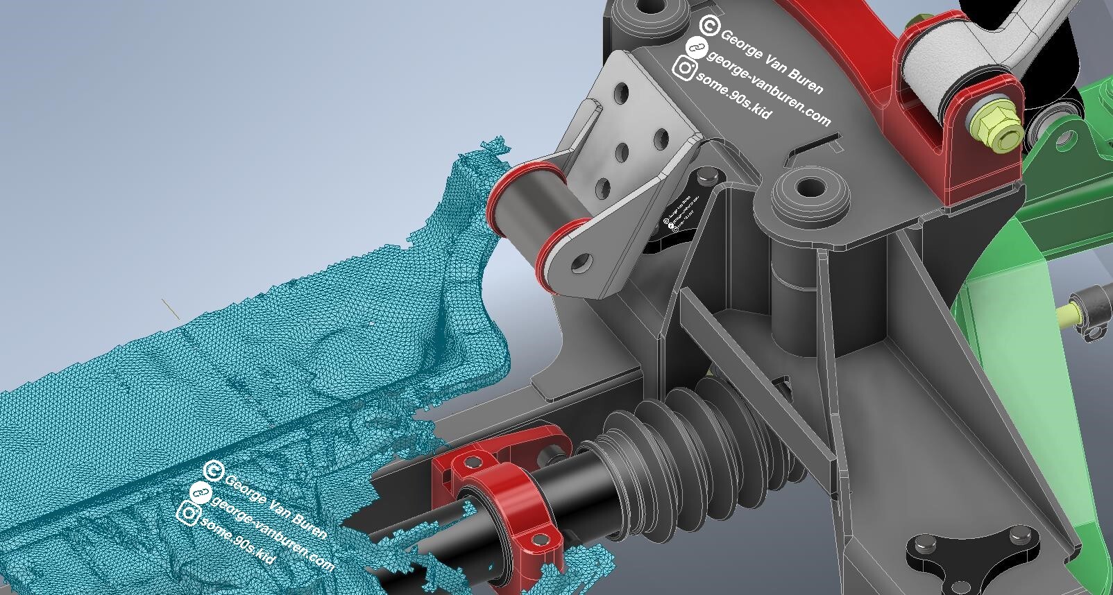
Engine and trans mounts doodled up, using universal application poly bushings from energy suspension. Was happy that I was able to make use of the 3d scanner for the trans mount, however the other side of the engine mount will have to be cardboard aided design as its much too tight to get reasonable scan data.
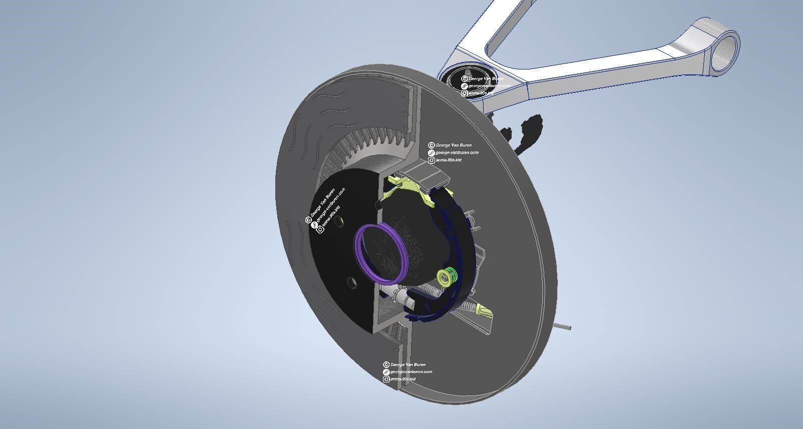
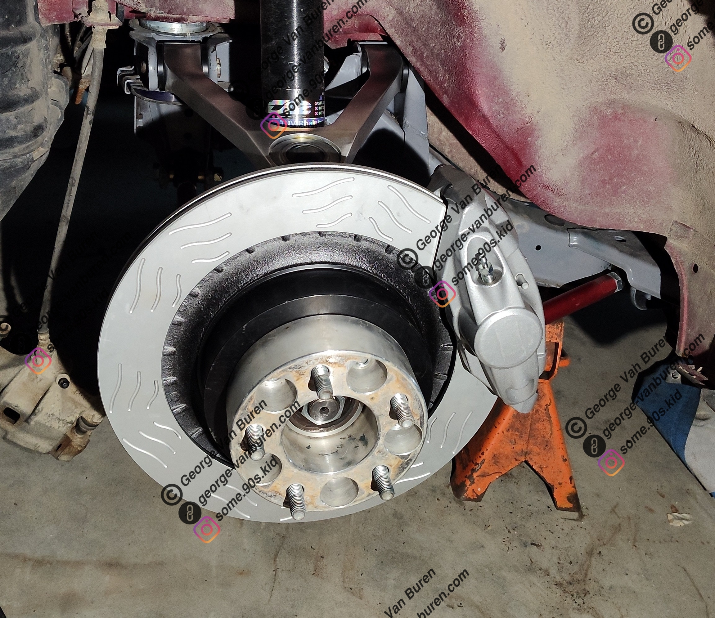
Have a rough design for the rear brakes as well to match the front brakes. Utilizing 370z Nismo rotors, calipers, and pads. Also had to use parking brake shoes from the Nissan and a hub ring to center the Nissan rotor on the Toyota hub. I chose these for brakes for a number of reasons over some of the more budget friendly swap options and on the market big brake kits. They're off the shelf parts, reasonably priced, and unlike the more affordable options that require less work they match front and rear, have better brake pad options, and the brake bias very closely matches that of the stock brakes.
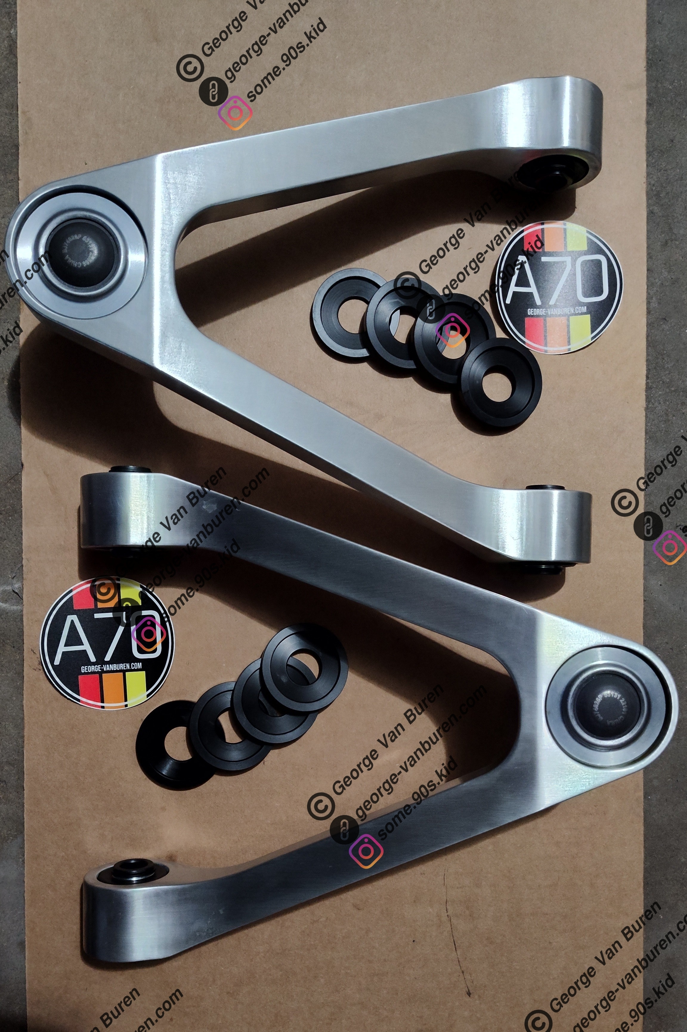
I assembled a set of rear upper control arms with uniball joints for my car and the rear brakes. Did a test fit with the wheels that came with the car (18x10 +40, 235/40/18) which cleared the brakes just fine.
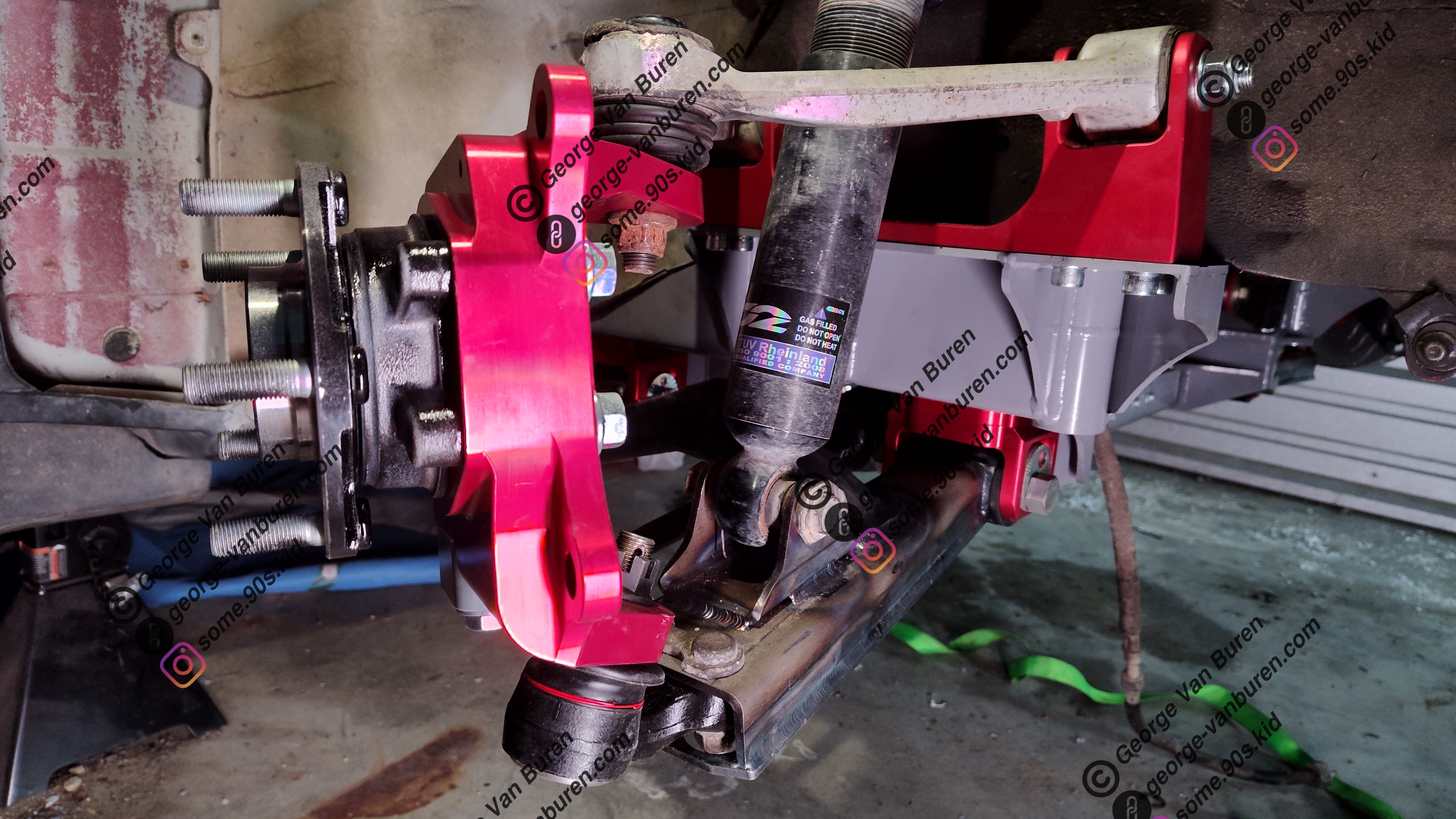
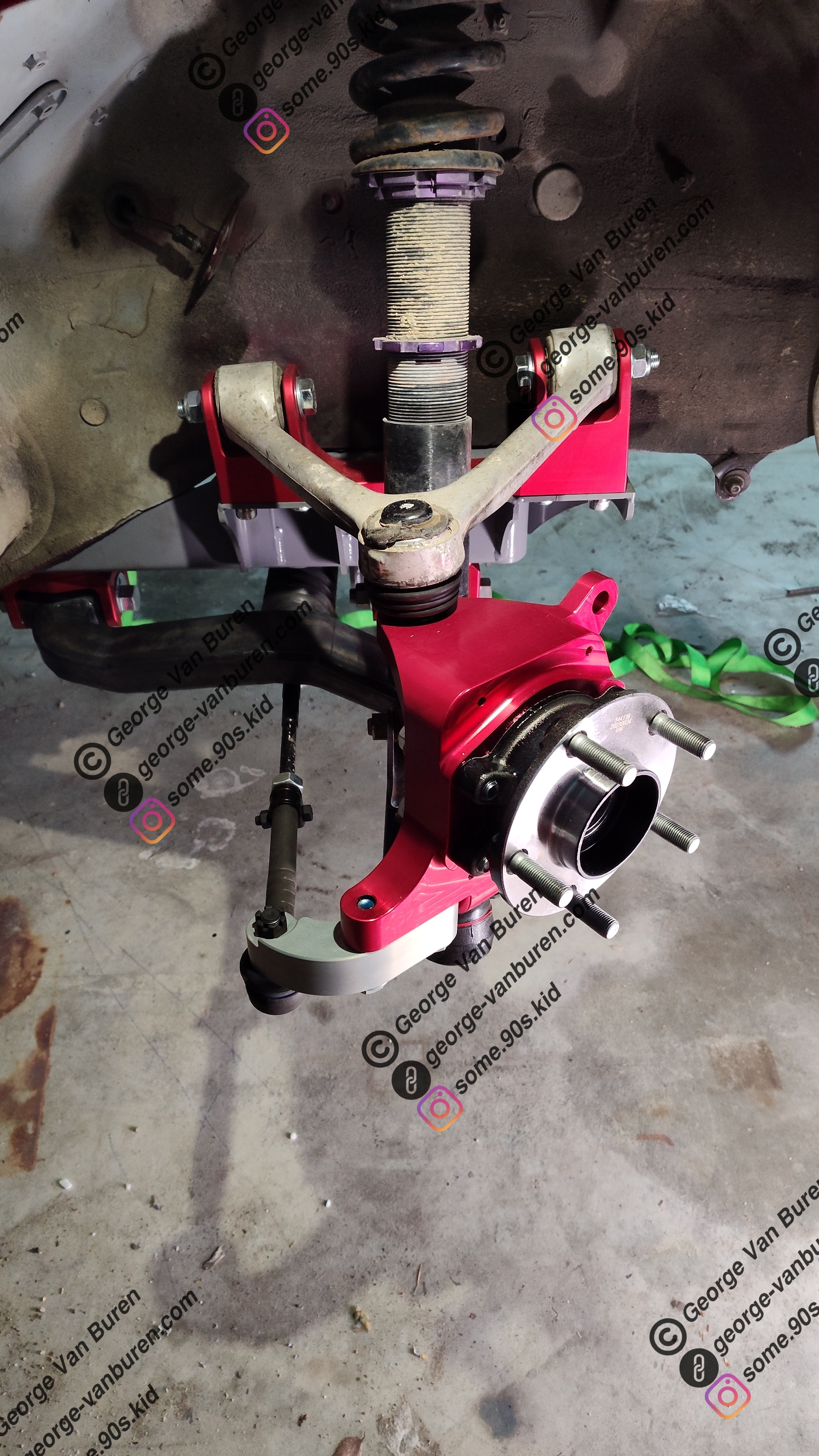
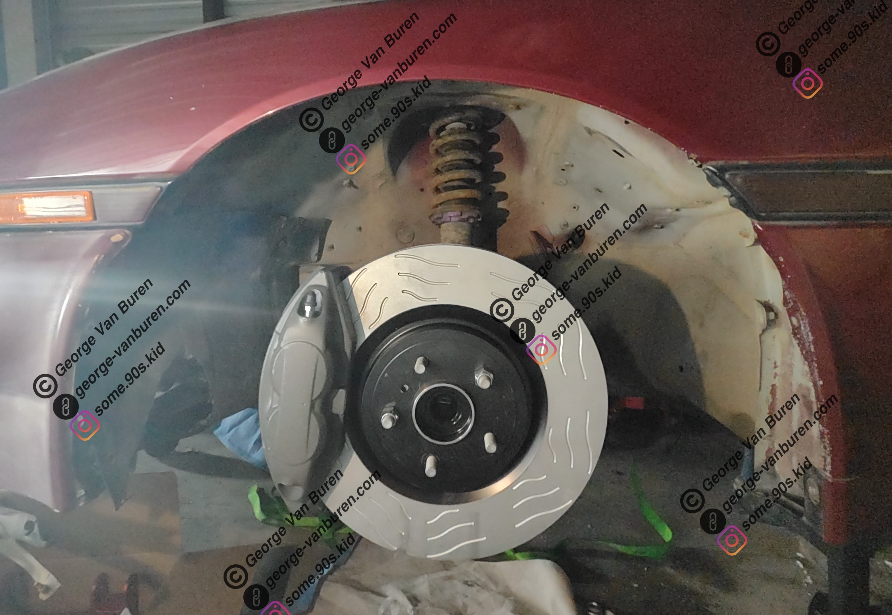
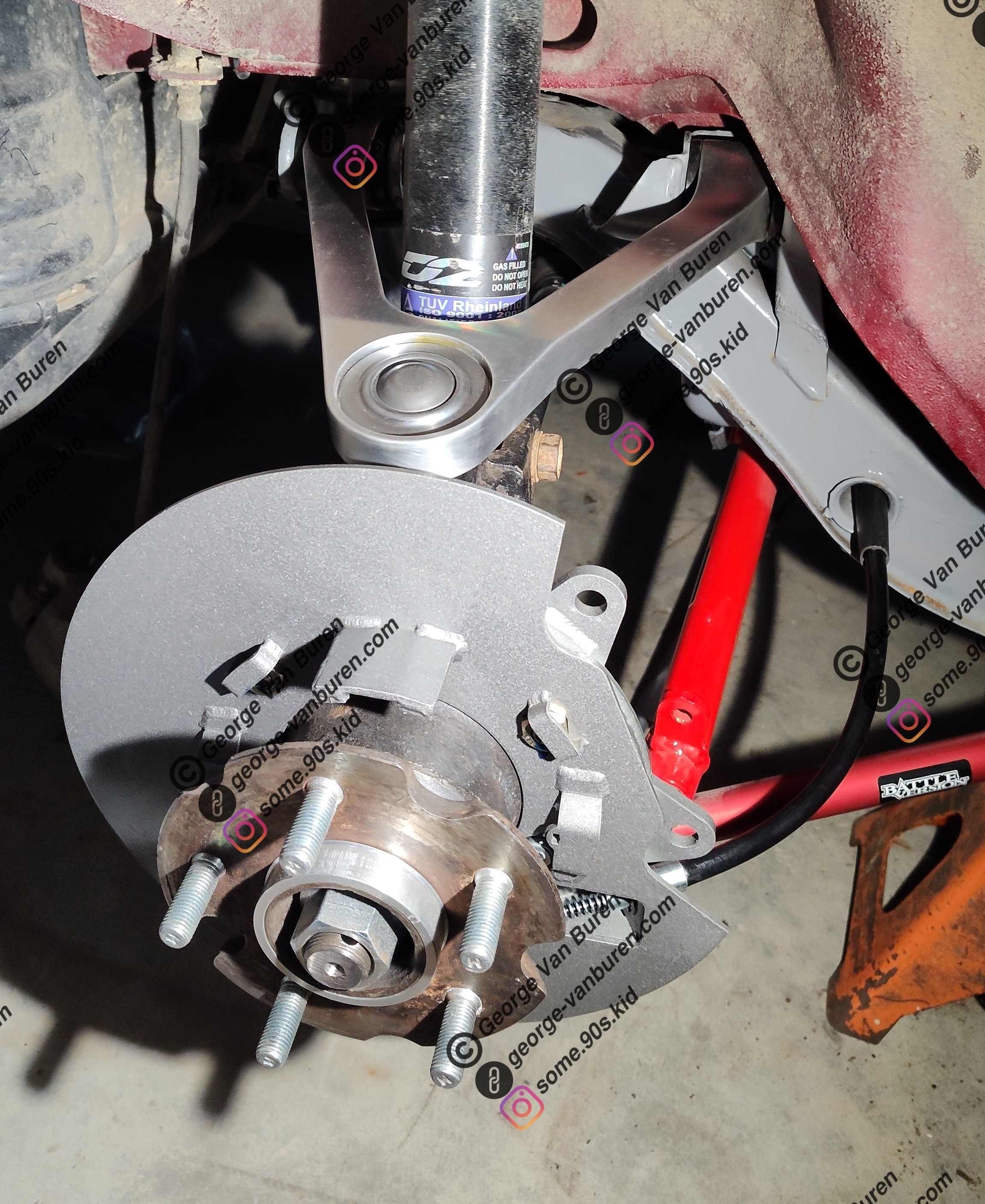
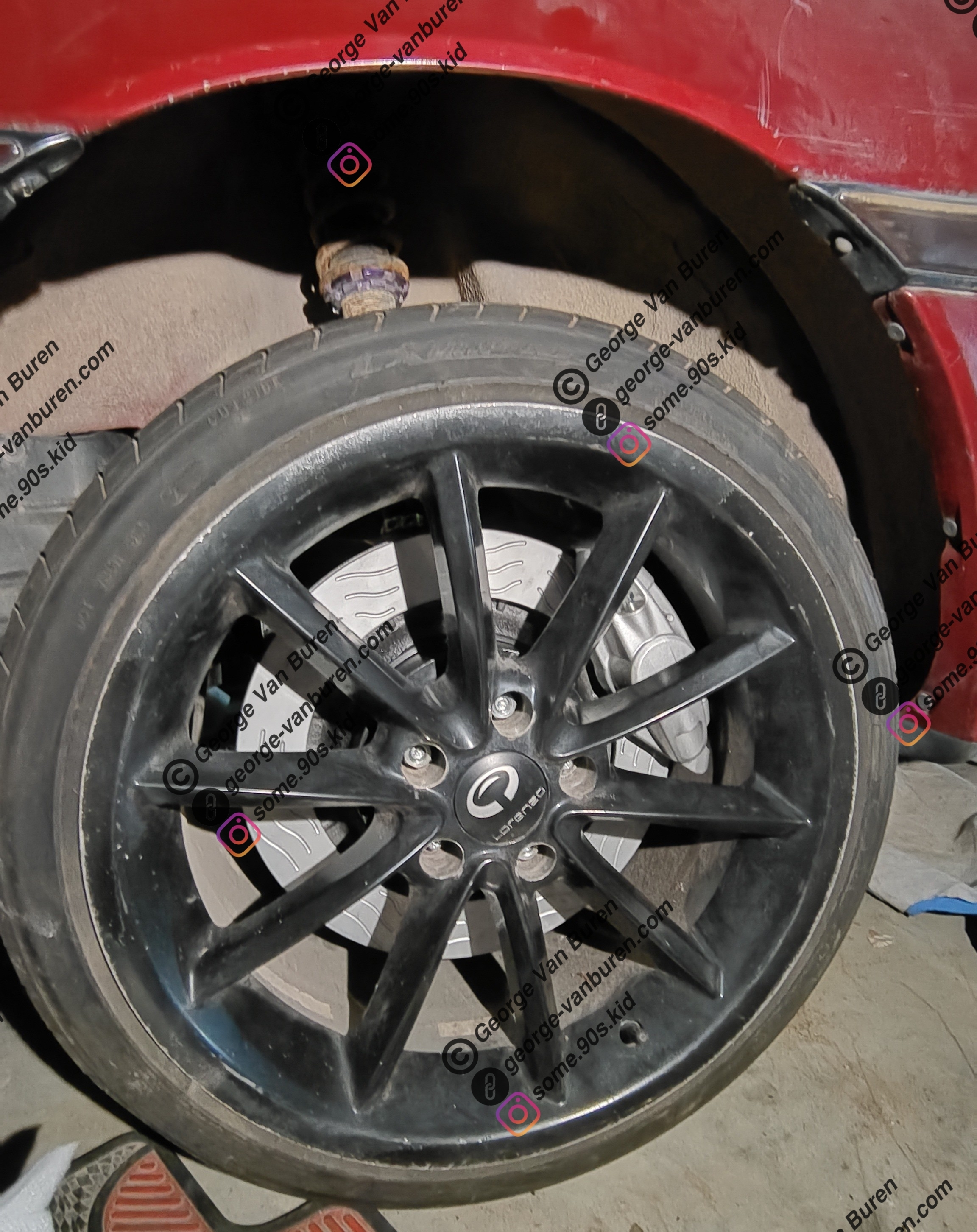
Front suspension was also assembled with the brakes, test fit with the same wheels (square setup) which did not fit due to the spoke design. the back side of the spokes contacted the outer face of the caliper. Pretty happy with how everything else fit however, went from S13 rack, S14 inner tie rod, A70 outer tie rod, to drop knuckle steering arm.
Transmission mounted
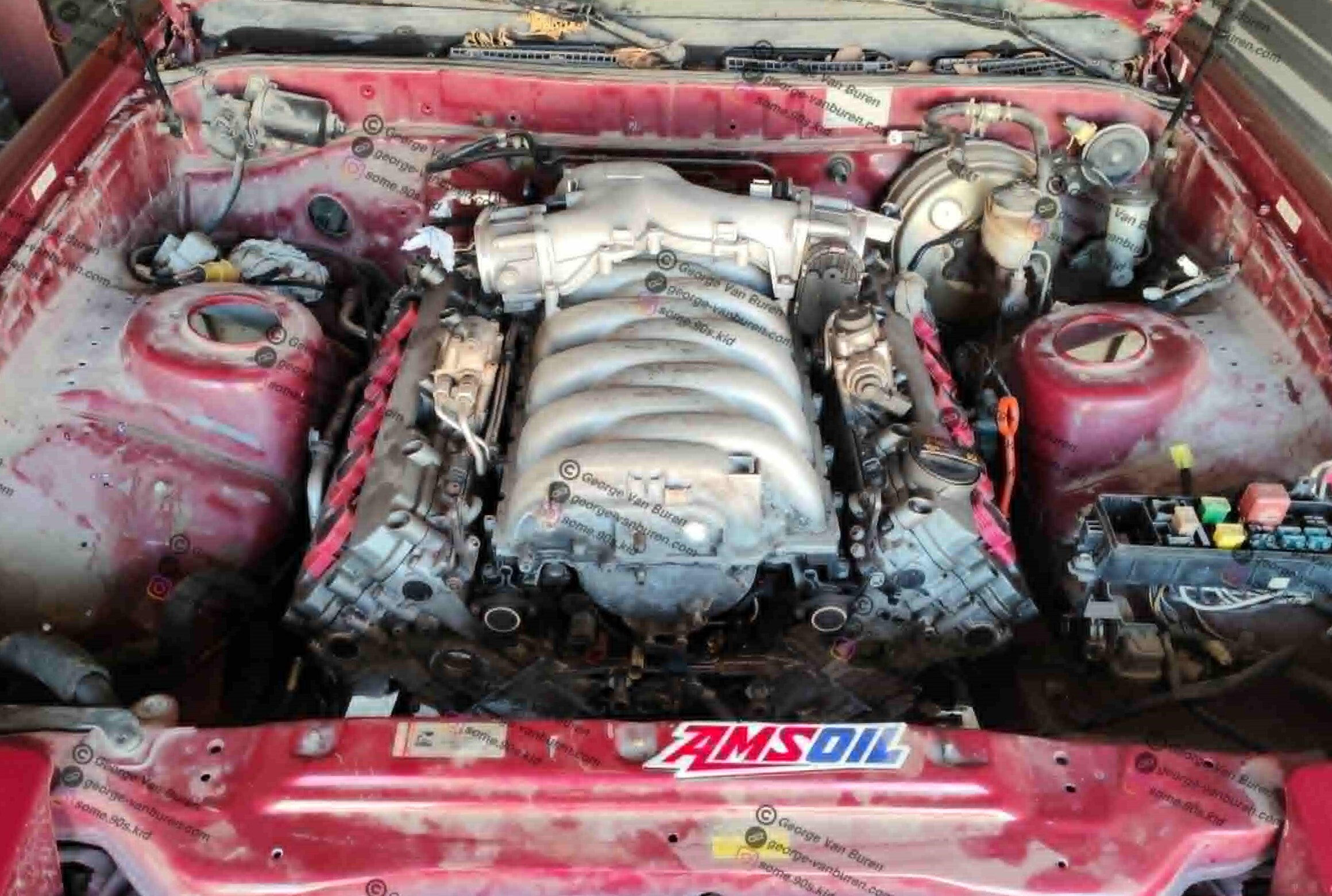
Engine mounted